


What is XTRA-N G3 charge controller?
The XTRA-N G3 series solar charge controllers are engineered to meet the increasing requirements of off-grid energy systems. These controllers include a built-in Bluetooth module for easy management via the EPEVER app.
Equipped with an advanced Maximum Power Point Tracking (MPPT) algorithm, the controllers optimize the tracking of the Maximum Power Point to maximize energy harvest across various environmental conditions. They are designed for efficient operation, featuring a three-stage charging mode that enhances battery lifespan and system efficiency while minimizing static power consumption.
The controllers are built with an IP33 ingress protection rating for reliable performance and include an isolated RS485 communication port to support diverse applications. They are compatible with multiple types of lithium batteries, providing the necessary safeguards to maintain safe battery operation across different use cases such as RVs, residential systems, and monitoring setups.
What is the naming convention of XTRA-N G3?
· Naming rules for XTRA-N G3 series
Models with the suffix ‘BLE’ indicate controllers with built-in Bluetooth functionality.
Certain models without this suffix are standard versions.


G3: This denotes that the product is from the 3rd generation of the XTRA series, indicating advanced features and improved performance from earlier iterations.
N: Represents a common negative system, which is a wiring configuration typically used for grounding and safety in electrical systems.
10: The number indicates the PV maximum open-circuit voltage. “06” corresponds to 60 volts, “10” to 100 volts, and “15” to 150 volts.
02: Battery rated voltage: Here, “2” signifies that the product can handle 12/24VDC battery systems, and “4” expands compatibility to 12/24/36/48VDC systems, showcasing the controller’s adaptability to different battery voltages.
1: This number indicates the controller’s maximum current capacity in amperes. “1” equals a 10A capacity, “2” is for 20A, “3” is for 30A, and “4” indicates a robust 40A, suitable for a range of power requirements.
XTRA: This is the series name.
XTRA-N G3 Main Features:
- Advanced MPPT technology & ultra-fast tracking speed, tracking efficiency is up to 99.5%
- Constant voltage output function
- Wider MPP(maximum power point) running voltage to optimize PV utilization
- Support multi battery types including lithium batteries
- Accurate recognizing and tracking of multi-peaks maximum power point
- Equipped with a stable self-activation function for the lithium battery
- Set the battery voltage parameters on the LCD
- Battery temperature compensation
- Built-in Bluetooth to adjust settings through EPEVER APP
- RS485 communication interface with optional 4G or Wi-Fi modules for remote monitoring
- Comprehensive electronic protections
- Dustproof and waterproof design with IP33 enclosure
- Low self-consumption, lower than 10mA
- Operation at full load without charging power reduced in the working temperature range
XTRA-N G3: Why is this model unique?
· Constant voltage output function
ØEnables direct load supply with sufficient PV energy
ØPrevents overshoot voltage with tailored protection values
ØProvides stability and compatibility for various lithium batteries
ØPrevents high voltage spikes during BMS cut-off
ØProtects load, inverter, and system integrity
In the daily operation of solar photovoltaic systems, the following reasons can lead to overvoltage, subsequently causing damage to the loads or controllers.
①If the BMS’s sensors or control units fail, they will not be able to properly disconnect the battery’s charge, leading to voltages exceeding safe thresholds.
②Improper matching and configuration of components within the photovoltaic system, such as solar panels, controllers, and inverters, can also cause system overvoltage. If the maximum output voltage of the solar panels exceeds the maximum voltage that the controller or battery can handle, overvoltage can occur.
③If components are aged or damaged and not dealt with in a timely manner, overvoltage can also happen.
④In cases of extreme high temperatures, the output of solar panels may be abnormal, which may also cause the system voltage to temporarily exceed the standard.
However, thanks to the constant voltage output function of the G3 series controllers, the device is compatible with different lithium batteries. Even if the BMS disconnects the battery due to overcharging or other concerns, the G3 can maintain uninterrupted power delivery to your loads. Indeed, it adjusts the output voltage to a safe level tailored to the specific requirements of your system. It promptly provide a stable voltage output, effectively preventing voltage spikes and safeguarding against potential damage to the equipment. Consequently, instead of experiencing harmful voltage jumps, your system continues to operate smoothly without any issues, ensuring that your loads remain powered and protected. Regardless of whether the battery is disconnected, your loads continue to receive power.
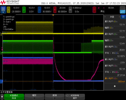
· Output over-current protection
ØIntelligent Over-current Detection: Immediate response to over-current scenarios
ØDynamic Load Management: Adjusts output to prevent system overload
ØEnhanced System Safety: Protects equipment from current-induced damage
ØContinuous Operation Assurance: Ensures uninterrupted power delivery during over-current
The following graph illustrates how the controller implements over–current protection. The pink line represents the load current, while the blue line represents the output voltage on the battery side. When an overcurrent situation occurs, the pink line (current) surges. The controller identifies the abnormal condition and swiftly cuts off the output voltage, disconnecting the load to prevent damage to the controller due to overcurrent. If there are no anomalies, the system returns to normal operation.
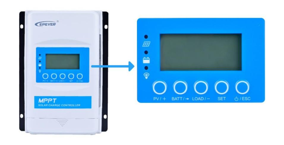
· XTRA-N G3 display unit
This series comes with an LCD screen for viewing real-time data and accessing key system parameters settings. It also features communication COM port enablement settings. By disabling this function, users can further reduce equipment consumption, extending system standby time. The following table illustrates the power consumption status when communication is enabled and disabled. The ultra-quiet operation is designed for the noise-sensitive environment.
| Low Power Consumption | |
| Communication enabled | Communication disabled |
| ≤15mA/12V (minimum10mA)
≤9mA/24V(minimum7mA) ≤7mA/48V |
≤8mA/12V
≤6mA/24V ≤5mA/48V
|
· Current limiting setting
When the charging current available from the PV side exceeds the charging current required by the battery, there is no need to reconfigure the PV panels. Instead, the charging current for the battery can be directly adjusted through the charge controller.
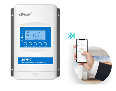
· Built-in Bluetooth module
The ‘BLE’ model with built-in Bluetooth do not require additional communication accessories. They allow real-time parameter reading and modification through the app, making the application more convenient. Additionally, it can meet various monitoring requirements by adding communication accessories ( MT52, PC communication cable, or WiFi module) via the COM port.
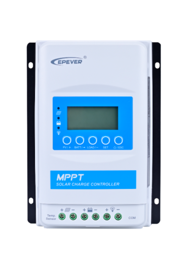
Components and Appearance:

- RTS port:If the temperature sensor is short-circuited or damaged, the controller will charge or discharge according to the setting voltage at 25 ºC (no temperature compensation).
- PV terminals:The solar power will be converted through this terminal. It allows the efficient transfer of solar-generated electricity.
- Battery terminals:This is the essential connection points for the battery, enabling energy storage.
- Load terminals: It can connect various electrical devices, facilitating the distribution of power to the intended appliances.
- RS485 communication port:It functions as a data exchange interface, supporting optional 4G or Wi-Fi modules for remote monitoring and enabling efficient communication between the system components over longer distances.
- Terminal protection cover:This cover acts as a safeguard for the terminals.
- Display units:It present essential information and data related to the system’s performance, making it easy for users to monitor and manage their energy setup.
- Mounting hole:Easy connection, efficient power.
How to setup a solar off-grid system with XTRA-N G3?
Step 1: Determine the installation location
Before installing, it’s crucial to assess the environmental conditions. Ensure that the controller is placed in a well-ventilated interior to guarantee ample airflow. Maintaining a minimum clearance of 150 mm from both the top and bottom edges of the controller promotes natural thermal convection.
- Never install the controller in a sealed enclosure with flooded batteries.
- Do not install in a confined area where battery gas can accumulate.
- When wiring the solar modules, the PV array can produce a high open-circuit voltage, so disconnect the breaker before wiring and be careful.

Step2: Wiring
Connect the system in the order of ❶battery > ❷load > ❸PV array Schematic Wiring Diagram, and disconnect the system in the reverse order ❸❷❶

Step3: Grounding
XTRA-N G3/ XTRA-N G3 BLE series are common-negative controllers; all the negative terminals can be grounded simultaneously, or anyone is grounded. However, according to the practical application, the negative terminals of the PV array, battery, and load can also be ungrounded. Still, the grounding terminal on the shell must be grounded. It effectively shields the electromagnetic interference from the outside and prevents some electric shock to the human body.
Step 4:Connect accessories
Connect the remote temperature sensor cable
Temperature Sensor
Remote Temperature Sensor Cable (Optional)
Step5: Connect the accessories for RS485 communication and powered on the controller
For this section, please refer to the manual for more details.
Load working modes:
Why we give you various load working modes to select? Because different modes allow users to control when their electrical loads are activated or deactivated based on specific conditions or preferences. Without these selection, the system would lack flexibility in managing power consumption and may not efficiently utilize available energy resources. Users can choose the operation of their loads to match their needs, optimize energy usage, and ensure system reliability.
① Manual Mode
In manual mode, the load is controlled manually.
② Light ON/OFF Mode
This mode activates the load based on light conditions and PV panel voltage.
③ Light ON/OFF + Timer
It allows the load to stay on for a specified period after sunset, depending on light and voltage conditions.
④ Real-time Control Mode
The load will be managed based on real-time conditions and requirements.
The following modes offer increased flexibility:
⑤ Mode 1 (night on and day off)
Mode 1 activates the load at night and deactivates it during the day.
⑥ Light ON/OFF + Timer Mode 2 (day on and night off)
Mode 2 activates the load during the day and deactivates it at night.
⑦ Always ON Mode
It keeps the load operational throughout the day.
Accessories:
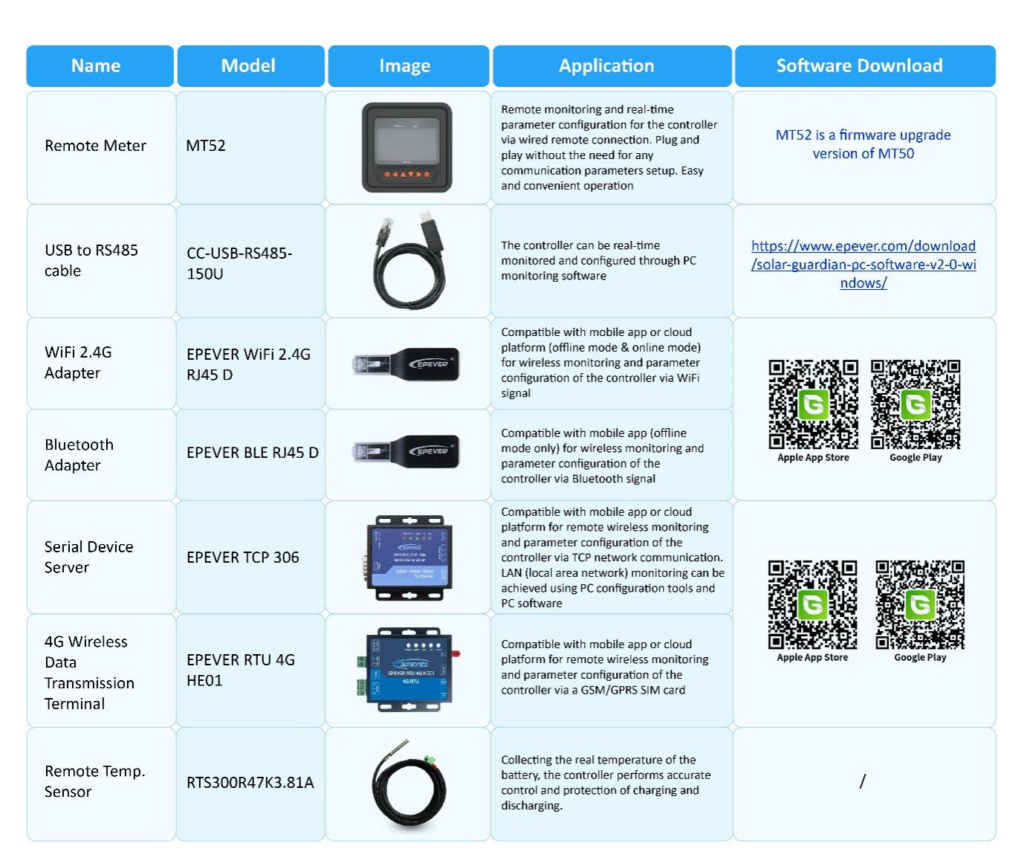
Explore our official website for more details. Here, you can discover comprehensive information about the product’s appearance and specifications.
Source: https://www.epever.com/advanced-mppt-charge-controller-xtra-n-g3/