


HPS-AHL for household energy storage
Introduction:
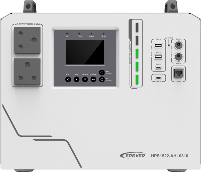
The new launch home battery backup HPS-AHL elevates your solar power system to new heights of performance. This all-in-one system with built-in lithium iron phosphate battery can meet your energy storage needs without the need for additional battery purchases. Additionally, the lithium battery is safe and durable, providing peace of mind in its usage.
HPS-AHL has 3 basic functions, including solar charging, utility charging and off-grid inverter. It also supports oil generator charging, bypass output, inverter output, and energy management. Diverse power supply types ensure stable electricity in any area and weather conditions, eliminating concerns about power shortages and outages.
The versatile range of AC and DC output interfaces can meet various load power requirements, making it highly convenient for power utilization. Plug and play, meeting various electricity demands.
The product also features MPPT charging capability and the DSP chip with an advanced control algorithm brings high response speed, reliability, and conversion efficiency. This product, with its outstanding performance and impressive sophistication, opens up boundless possibilities across various industries.
Overview:
HPS-AHL features the newly optimized MPPT tracking technology, enables fast-tracking of the PV array’s Max. power point in various situations, obtaining maximum energy in real-time.
The built-in lithium battery adopts a three-stage charging method (Bulk Charging, Constant Charging, and Float Charging) to ensure the safety of battery.
The HPS-AHL series offers multiple charging and output modes to suit different scenarios. The fully smart digital DC to AC inverting process utilizes advanced SPWM technology, outputting a pure sine wave and converting DC power to AC power. It is suitable for household appliances, power tools, industrial equipment, audio systems, and other electronics.
Charging the AC power with PFC technology ensures a high power factor, enhancing energy efficiency and promoting optimal energy consumption.
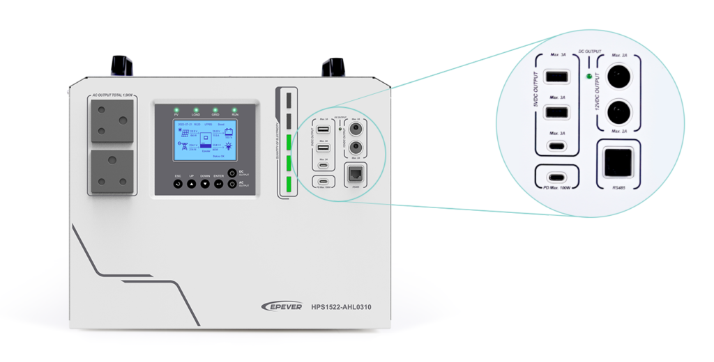
Furthermore, this device includes multiple DC output ports, such as 5V/3A ports and 12V/2A ports. Additionally, two Type-C dedicated ports (5V/3A and 100W PD) cater to the fast charging needs of mobile phones and notebooks.
The communication interface with the standard Modbus protocol allows end-users to expand their applications and meet different monitoring requirements.
The HPS-AHL provides high-quality, high-stability, and high-reliability electric energy, enhancing the power supply efficiency of the solar system for end-users.
Features:
- Circuit breaker on battery output for battery safety.
- Advanced MPPT technology, with Max. tracking efficiency higher than 99.5%.
- Circuit breaker on PV input for equipment safety.
- AC input overload relay for disconnecting from the power grid when the fault occurs.
- PFC technology reduces the demand on the power grid capacity.
- Bidirectional high-frequency transformer isolation topology.
- Load continuously operates at full power for a long time.
- Pure sine wave output.
- EMC design on AC output to avoid interference with AC load.
- Large-sized LCD for better status monitoring.
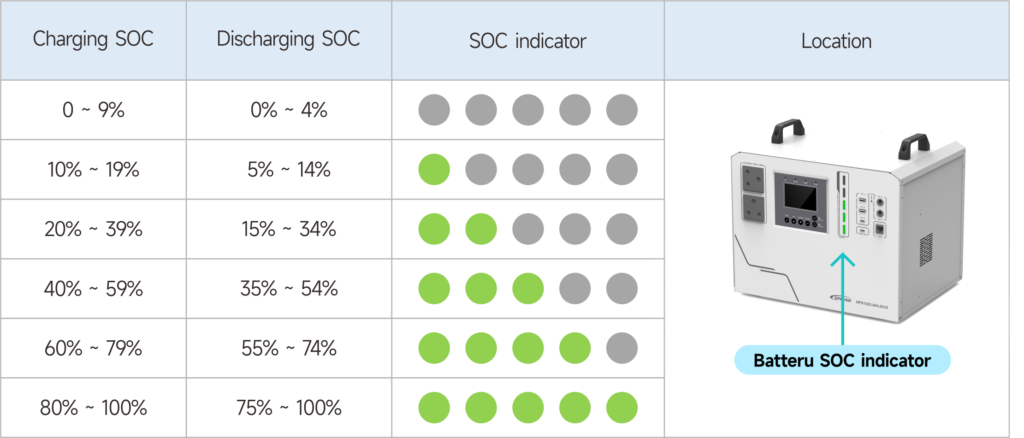
- Intuitive display of battery SOC via 5-bar indicator lights.
- Multiple DC output ports (5V/3A ports, 12V/2A ports, Type-C ports).
- RS485 communication interface with optional 4G or Wi-Fi modules for remote monitoring.
- Built-in Bluetooth to adjust settings through the EPEVER APP.
- Built-in LiFePO4 lithium battery.
- Comprehensive electronic protection.
- Excellent dust-proof performance with separate compartment design.
Understanding the Naming Convention:
Our product model names are designed to provide you with a brief overview of the features and specifications of each device.
Now, let’s dissect the model HPS2522-AH0610:
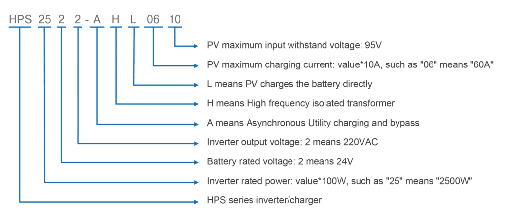
- HPSSeries: This prefix is the series’ name. S means energy storage system.
- “25”: The number25 represents the inverter’s rated power in hundreds of watts. Here, “25” translates to a rated power of 2500 watts or 2.5 kilowatts.
- “2”: The first single digit“2” represents the battery rated voltage. “2” signifies a 24V system.
- “2”: The second single digit “2” means the inverter output voltage. “2” corresponds to an output of 220VAC, suitable for many AC appliances.
- “A”: It means of asynchronous utility charging and bypass. During utility charging, the inverter cannot output power in reverse.
- “H”: This corresponds to high frequency isolated transformer.
- “L”: It means PV charge the battery directly.
- “06”: The next two digits “06” represent the maximum charging current times ten. Therefore, “06” indicates a maximum charging current of 60 amperes.
- “10”: The two digits as a part indicate the maximum input withstand voltage of the PV is 95V.
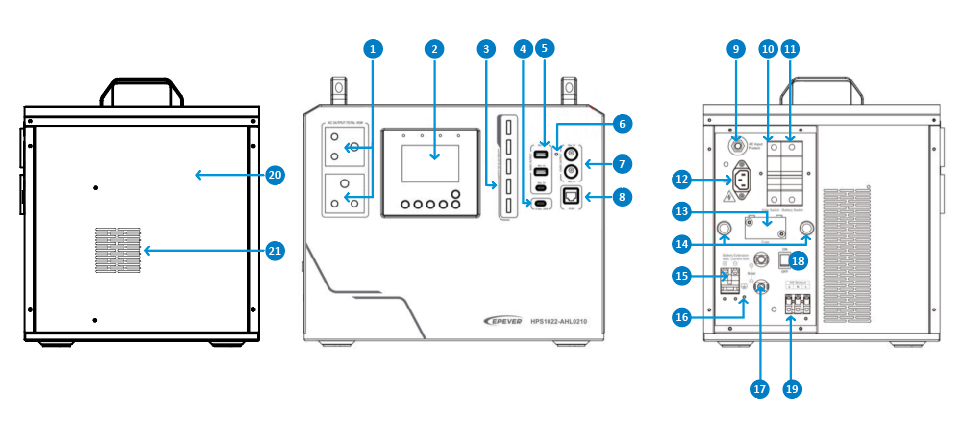
Components and appearance:
For this discussion, the model HPS1022-AHL0210 serves as a reference. For detailed insights or information about different models, please refer to the relevant manual.
| NO. | Instruction | No. | Instruction |
| 1 | AC outlet | 12 | AC input port |
| 2 | LCD display | 13 | Extension battery fuse |
| 3 | Battery SOC indicator | 14 | Outlet holes |
| 4 | Type-C port (100W PD) | 15 | Extension battery terminal |
| 5 | 5V/3A output port*3 | 16 | Grounding terminal |
| 6 | DC output indicator | 17 | PV input terminals |
| 7 | 12V/2A output port*2 | 18 | Power switch |
| 8 | RS485 com. port | 19 | AC output terminal |
| 9 | Utility bypass overload relay | 20 | Battery container |
| 10 | PV input circuit breaker | 21 | Cooling fan |
| 11 | Battery output circuit breaker |
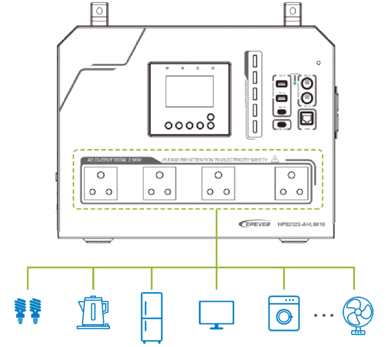
1 AC Outlet: With the ability to power various devices, including smartphones, laptops, tablets, household appliances, and other electronics, this outlet supplies the required energy.
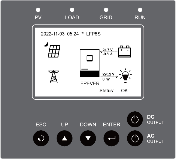
2 LCD Display: The user-friendly screen allows users to easily adjust and monitor system parameters.
3 Battery SOC indicator: Located on the front of the device, there are 5-bar LED indicators are displaying the battery SOC for charging and discharging.
4 Type C Port: Versatile and adaptable, this port offers power solutions for a wide array of devices, such as smartphones, tablets, laptops, and cameras.
5 5V/3A Output Port: Designed specifically for efficient DC power delivery, this port caters to a variety of appliances and devices that require a direct current power supply.
6 DC Output Indicator: A handy feature that provides real-time status updates, this indicator illuminates when a DC power connection is active.
7 12V/2A Output Port: Tailored to accommodate a 12V DC load connection, this port supplies power to devices operating on this specific voltage.
8 RS485 Communication Port: This interface enables local Modbus and remote system supervision by integrating optional 4G and WiFi modules, facilitating a seamless and remote user experience.
9 Utility bypass overload relay: Crucial protective component is integrated into the system to ensure the safety and stability of the power supply.
10 PV Input Circuit Breaker: Designed to receive solar energy input from PV panels, this configuration includes an automatic protective mechanism that guards against overcurrent or surges, ensuring the integrity and longevity of the entire system.
11 Battery Output Circuit Breaker: Crafted to guarantee safe battery operation, this feature instantly trips open in the event of overcurrent or short circuit situations, offering immediate system and battery protection.
12 AC Input Port: This interface links the device with utility power or a generator, permitting AC power input from these sources and guaranteeing a consistent power supply.
13 Extension Battery fuse: This is an essential safety component that protects the battery. It is designed to safeguard against overcurrent or short circuit situations that may arise in the battery circuit.
14 Outlet holes: These outlet holes are strategically positioned ports that enable the connection of various electronic devices and appliances to the power supply.
15 Extension Battery terminal: This terminal is available for battery expansion or substitution, offering added flexibility. For detailed guidance, please consult the manual.
16 Grounding Terminal: This is essential to divert electrical currents away from sensitive equipment and ensure that any potential electrical faults are safely directed to the ground.
17 PV input terminals: These are dedicated ports for connecting solar panels to the device. It can facilitate a seamless and efficient connection between the PV panels and the system
18 Power switch: This switch provides flexibility and ease of operation, enabling users to optimize the system’s performance according to different scenarios and power requirements.
19 AC output terminals: These terminals ensure a stable and reliable power supply to connected loads. It delivers the converted AC power from the device to various electrical devices and appliances.
20 Battery container: The container are protective enclosure designed to safeguard batteries, ensuring their safe and efficient operation.
21 Cooling fan: It is responsible for dissipating excess heat generated during operation, preventing overheating, and ensuring the longevity and reliability of the system.
Multiple Charging and Output modes:
① Charging modes:
- PV charge only: In this mode, the battery is charged solely from the solar panels without relying on an external power source. It is suitable for areas without access to the grid and where solar energy is abundant.
- PV (solar) Priority: This mode prioritizes solar power, allowing the system to maximize the utilization of solar energy and reduce dependence on the grid. This helps lower energy costs, especially in areas with ample sunlight, significantly reducing electricity expenses.
- PV+ Utility Charge: This mode provides a more stable power supply. Solar panels take precedence in supplying power, and when solar energy is insufficient or during nighttime, the system switches to grid power. This ensures a continuous and stable power supply even when solar panels are unable to operate or sunlight is limited.
② Output modes:
- Inverter output:The inverter output is designed to convert direct current (DC) from a power source, such as solar panels or batteries, into alternating current (AC) for use in electrical appliances. This is particularly useful in off-grid or hybrid systems where DC power needs to be transformed into AC power.
- Bypass output:bypass output provides an alternative route for the power to flow directly from the input source to the output load, bypassing the inverter.
HPS-AHL Scenarios:
Our innovative HPS-AHL all-in-one power system enables people in challenging and remote locations to access electricity effortlessly. Analyzing the consumption data outlined in the table reveals how efficiently this inverter/charger can fulfill the daily energy requirements of a household.
Here we choose HPS1022-AHL0210 as our model.
| Appliance | Average Power
Consumption (Watts) |
Hours Used Per Day | Total Consumption (Watt-hours/Day) |
| Rice Cooker | 600 | 1.6 | 960 |
| Television Set | 100 | 10 | 1000 |
| Coffee Maker | 900 | 1.1 | 990 |
| Electric Oven | 800 | 1.3 | 1040 |
| Impact Drill | 1100 | 0.9 | 990 |
| Car Refrigerator | 62 | 16 | 992 |
The total daily consumption amounts to 5972 Watt-hours which is based on the inverter capacity, feasible and fully covered.
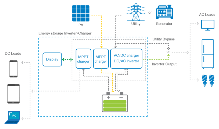
Schematic diagram of connections in the HPS-AHL series:
This topology diagram provides a clear representation of the operating mode of this home battery backup system. The system’s design is capable of meeting various customer needs for electricity consumption and energy storage.
Firstly, the all-in-one system is directly connected to the PV array, supplying power to DC loads through an MPPT controller, and storing the converted energy from the solar panels in the built-in LiFePO4 battery.
The inverter converts DC power obtained from the battery to AC power. The device can realize 2 output modes: the utility bypass output and the inverter output.
In periods of insufficient sunlight or during the night, the system can switch to obtaining power from the utility or an external generator. This ensures a continuous power supply to the connected loads, making it a reliable power solution for any situation.
Users can directly monitor the real-time status of the system through the LCD screen and the 5-stage SOC indicator. Additionally, it can be integrated with the RS486 communication interface, equipped with various modules, and enable cloud monitoring.
This diagram illustrates that the system can support a variety of energy storage and electricity consumption scenarios, meeting diverse needs.
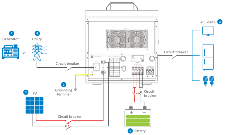
HPS-AHL Wiring:
Connect the HPS-AHL in this order:
❶Ground > ❷load > ❸PV array > ❹Utility generator > ❺optional accessories
Don’t connect the device in the reverse order.
The following wiring sequence is illustrated in the appearance of “HPS2522-AHL0610.” For wiring positions of other models, please refer to the actual product appearance.
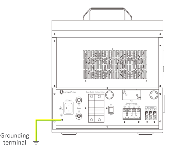
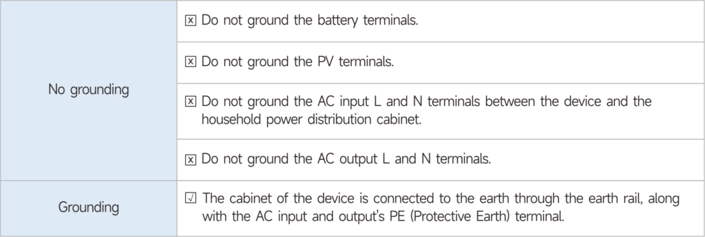
1. Grounding:
The device comes with a dedicated grounding terminal that requires a reliable grounding connection. The grounding wire size should align with the recommended AC output wire specification. For optimal grounding, it is essential to position the grounding connection point as close as possible to the device, while keeping the total grounding wire as short as feasible.
2. Connect the AC loads:
- Connect the AC load to the AC outlet
 Connect the AC load by the AC output terminal
| Silk-screen | Abbreviation | Name | Color |
| L | LINE | Live wire | Brown/black |
| N | Neutral | Neutral line | Blue |
| PE | Ground line | Yellowish-green |
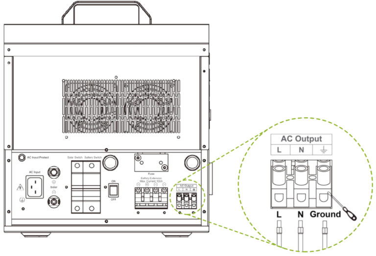
Note: The AC output terminal on the back of the product is suitable for AC loads that are not frequently unplugged.
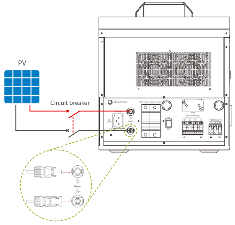
3. Connect the PV loads:
Caution: Suppose the device is used in an area with frequent lightning strikes. In that case, it is recommended to install an external surge arrester.
4. Connect the utility or generator:
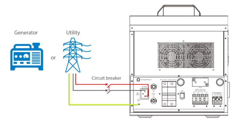
5. Connect optional accessories:
- Connect the communication module
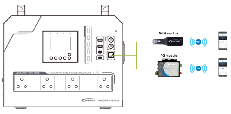
Connect the WiFi module or 4G module to the RS485 com. port (when connecting the 4G module, an additional power supply is needed). End-users can remotely monitor the device or modify related parameters on the phone APP. For detailed settings, refer to the WiFi module or 4G module user manual.
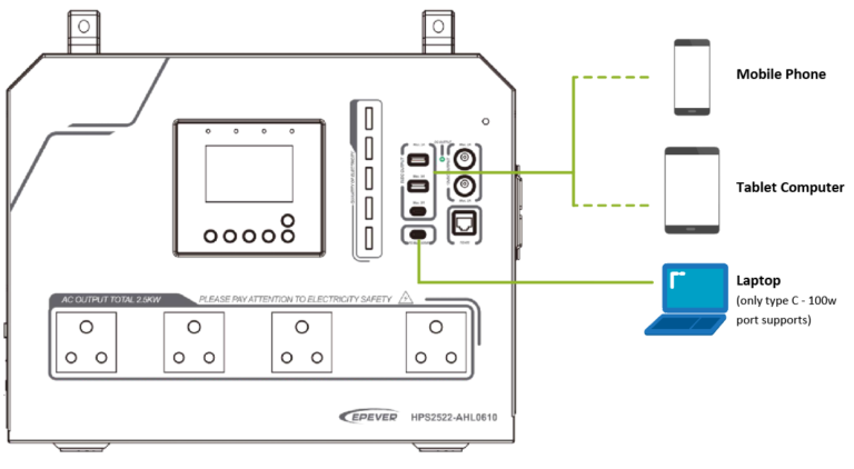
2. Connect the mobile phone or PC
Charging the mobile phone, tablet computer, or laptop by the 5V/3A or Type-C (100W PD) port.
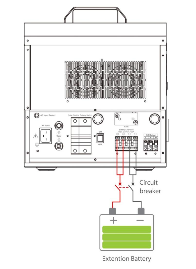
 3. Connect the extension battery
The circuit breaker must be installed on the external battery side. For selection, please refer to the manual. The external and internal batteries can be connected in parallel when their voltage is the same.
LCD screen instrucion:
Note: The display screen can be viewed clearly when the angle between the end-user’s horizontal sight and the display screen is within 90°. If the angle exceeds 90°, the information on the display screen cannot be viewed clearly.
Home screen:
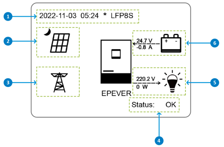

This device provides two default working interfaces:
- Ordinary User Interface
- Administrator Interface
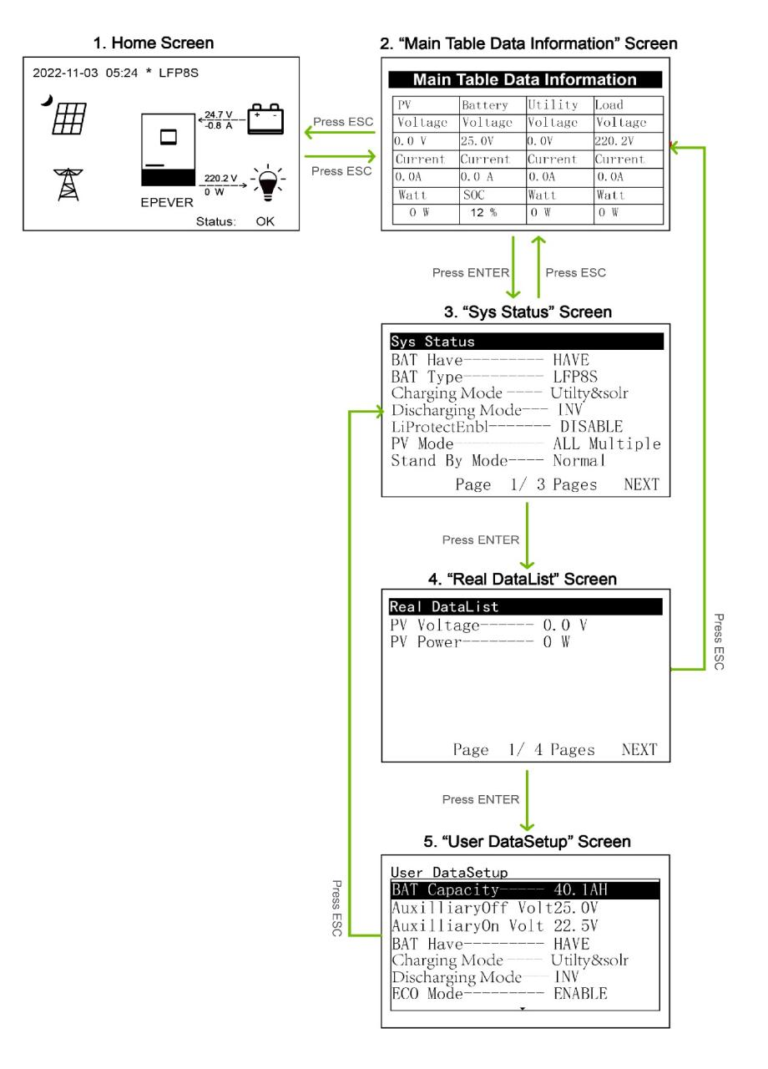
Ordinary User interface
After powering on the device, the home screen shows up. Click the “ESC” button to enter the “Main Table Data Information” screen. Click the “ENTER” button to enter the next interface, or click the “UP/DOWN” button to browse the current screen display.
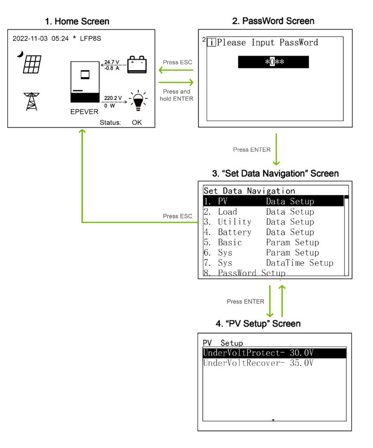
Administrator interface
After powering on the device, the home screen shows up. Press and hold the “ENTER” button to enter the password interface. Input the password correctly to check all parameters or modify them.
Working Modes:
Scenario A: Both PV and Utility are available
Scenario B: PV is available, but the Utility is not available.
Scenario C: The PV is not available, but the Utility is available.
Scenario D: Both PV and Utility are not available.
Here we will show you the Scenario A
(Please check for other scenarios in the product manual)
- Charging Mode: “Solar”& Discharging Mode: “Inverter”
1 When the PV power is greater than the load power, the PV charges the battery and supplies extra power to the load.
2 When the PV power is lower than or equal to the load power, the PV will not charge the battery, the battery will cut in to supply power to the load together with the PV.
3 Any of the following is satisfied, the Utility supplies power to the load and the PV charges the battery.
- The battery voltage is lower than or equal to the LVD value.
- The battery SOC is lower than or equal to the LED value.
- Charging Mode: “Solar”& Discharging Mode: “Bypass”
1 When the PV power is greater than the load power, the PV charges the battery and supplies extra power to the load.
2 When the PV power is lower than or equal to the load power, the Utility will cut in to supply power to the load together with the PV, and the PV charges the battery simultaneously.
3 When the device enters the float charging status and the battery voltage is lower than or equal to the FCV value, the PV charges the battery and supplies extra power to the load.
- Charging Mode: “Solar prior” & Discharging Mode: “Bypass”
1 When the PV power is greater than the load power, the PV charges the battery and supplies extra power to the load.
2 When the PV power is lower than or equal to the load power, the Utility supplies power to the load, and the PV charges the battery.
3 Any of the following is satisfied, the Utility and PV charge the battery, and the Utility supplies power to the load simultaneously.
- The battery voltage is lower than or equal to the AON value.
- The battery SOC is lower than or equal to the UCO value.
- Charging Mode: “Utility & solar”& Discharging Mode: “Bypass”
1 When the PV power is greater than the “load power+(MCC*battery voltage),” the PV charges the battery and supplies extra power to the load.
2 When the PV power is lower than or equal to the “load power+(MCC*battery voltage),” the Utility will cut in to supply power to the load together with the PV, and the PV charges the battery simultaneously.
Conclusion:
When it comes to power needs, the HPS-AHL all-in-one power system redefines the way we harness and utilize energy. Its exceptional performance, versatility, and advanced features make it a game-changer in various scenarios, from remote communities seeking enhanced living standards to households looking for reliable energy storage solutions.
Whether you’re powering your daily life, your essential appliances, or exploring off-grid living, the HPS-AHL is your trusted partner in the quest for clean, sustainable energy.
HPS-AHL also prioritizes reliability and stability. Its advanced cooling system and dependable hardware components ensure prolonged, stable operation, minimizing potential failure risks. This means users can confidently rely on HPS-AHL.
Check the product page for more information.