


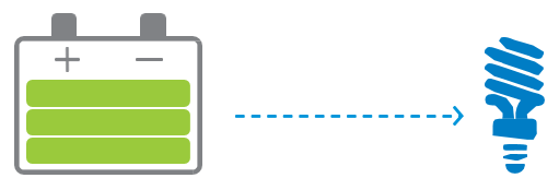
Inverters are employed to convert the DC power to AC power, providing the required voltage and frequency at the output. Inverters can be considered as power adapters. So they are considered as one of the important parts of a photovoltaic system, which supplies AC power for any appliance.
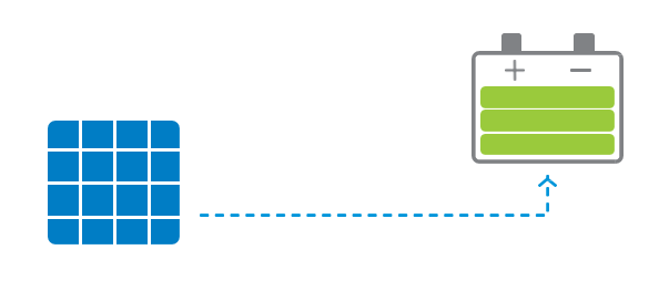
Charge controllers are also utilized to convert the solar energy from the panels to electricity, which is essential to charge the batteries in a PV system. Solar chargers get the electricity from the solar panels and control for everything, to make sure that the batteries are charged most efficiently and healthily.
Sometimes, the amount of energy absorbed by the solar panels is not enough to charge the battery for the proper operation of household appliances. Therefore, an additional source of energy is necessary to provide energy for the photovoltaic system. A hybrid charger/inverter puts the operation of an inverter and a charge controller together which is an all-in-one solution. However, this is not the only advantage of hybrid devices. In this article, we will get to know more about hybrid inverters/chargers and their advantages.
As mentioned, the inverter converts DC (battery) power into AC power and then passes it along to the appliances. An inverter/charger does the same; however, it is also capable of receiving the charge from external AC sources. When the input AC power is unavailable, a hybrid inverter/charge switches to battery mode. This is similar to Uninterrupted Power Suppliers (UPS) functions.
The UPOWER series of EPEVER is a new type of so-called inverter/charger, combining the solar & utility/ external AC input and providing means for a more reliable solar off-grid system.
UPOWER, adopts a multi-core processor design and an advanced MPPT control algorithm to enhance the capabilities of the solar set. It has the following features:
- High response speed
- High reliability and
- High industrialization standard.
It offers four charging modes including:
- Solar priority
- Utility priority
- Solar and
- Utility & Solar
Two output modes for Battery and Utility enable this device to meet various application demands. The up-to-date optimized MPPT tracking technology is adopted for the PV charging modules. It can quickly track the maximum power point of the PV array in any environment and acquire the maximum energy of solar panels in real time.
The advanced control algorithm is adopted for AC-DC charging modules. It realizes fully digitalized double closed-loop control for voltage and current, with high a high-accuracy control system.
The input range of AC voltage is wide enough to cover different types of sources. The output DC charging voltage/current is continuously adjustable in a certain range, and the complete input/output protection functions can offer a stable and reliable charging profile and charging protection for the batteries. This feature will lead to high charging conversion efficiency, which is more than 98% in all types of EPEVER UPOWER series. Besides, the power loss is minimized by the efficient AC-DC conversion. The DC-AC module is based on full digital and intelligent design. It adopts the advanced SPWM technology, resulting in a pure sine wave output and converts 24/48VDC to 220/230VAC, suitable for AC loads of household appliances, electric tools, commercial units, electronic audio, and video devices, etc.
The product adopts a 4.2-inch LCD display design, which displays real-time operational data and parameters. Comprehensive electronic protection functions ensure the highest level of safety and stability.
Features of EPEVER UPOWER Series Inverter/Charger
In this section, we will introduce the features of UPOWER series, which make them a proper choice for cold and cloudy climate conditions. Such places suffer from lack of a clear sky or sunny days, so for home appliances, which need solar power to work, an additional power source is necessary. UPOWER series benefit from the additional power sources, which can be an AC utility or power generator. The prominent feature of the UPOWER series is to combine the external AC power with solar power to enhance the reliability of the system. In places with higher rates of cloudy sky, it’s not efficient enough to use the external generator all the time in terms of cost and maintenance. This ensures efficient use of the solar system while reducing the run time and costs of external power sources. Cold and cloudy climate conditions restrict the application of solar energy in noticeable parts of the year, so the external AC power source or electrical generator provides energy for the household appliances when the amount of solar energy is not enough for the proper performance of the appliances.
Some of the main features of EPEVER UPOWER Series Inverter/Chargers are highlighted here which implies the priorities of these inverter/chargers over conventional ones:
- Adoption of the advanced SPWM technology, with pure sine wave output.
- Fully digitalized voltage and current double closed-loop control.
- Advanced MPPT technology, with efficiency no less than 99.5%.
- Advanced control algorithm, with efficiency no less than 98%.
- LCD design that enables the realtime display of system operating status.
- Provided with common interface and advanced interface.
- Multiple LED indicators instantly indicate the operating state of the system.
- 2P circuit breaker provided at the utility input end.
- Independent control of AC output by AC OUT button.
- Battery temperature compensation function.
- Extensive Electronic protection.
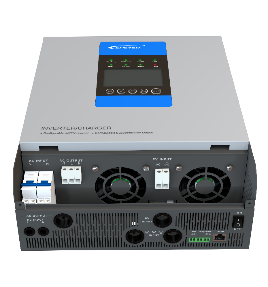
Structure of the EPEVER UPOWER Series Inverter/Charger
In this section, the structure of UPOWER series inverter/chargers and their various ports and terminals will be discussed to help the proper operation and wiring of solar systems.
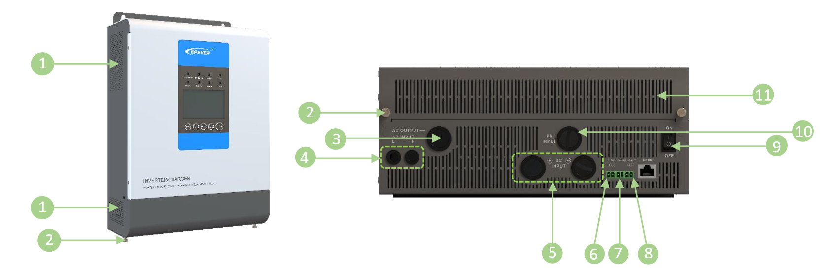
| 1 | Ventilation | 7 | Relay interface |
| 2 | Captive screw (2 pcs) | 8 | Remote interface |
| 3 | AC output terminals | 9 | Inverter/charger switch |
| 4 | Utility input terminals | 10 | PV input terminals |
| 5 | Battery input terminals | 11 | Terminals cover |
| 6 | RTS★ interface |
1- Ventilation: UPOWER adapts a smart temperature controlled cooling fan, helping the system to remain in a reasonable temperature range. However, external ventilation is highly recommended if the device is mounted in an enclosure. Thus, it should never be installed in an enclosure with flooded batteries! Battery fumes from vented batteries will corrode and destroy the inverter/charger circuits.
2- Captive screws: It helps to open the enclosure to get access to the main interface of its PCB.
3- AC output terminals: The protected AC outputs of the device. The protections are: Utility input overvoltage and Utility input under-voltage
4- Utility input terminals, which are protected.
5- Battery input terminals: which are protected against Battery overvoltage and battery over-discharge
6- RTS interface remote temperature sensor enables the system to activate the protection mode against battery overheating.
7- Relay interface: Smart relay interface, which switches the external AC generator ON based on the current battery capacity.
8- Remote interface: To turn ON and off the inverter remote.
9- Inverter/Charger switch: This turns the system ON/OFF.
10- PV input terminals: which are protected. These protections are PV limit Current, PV short circuit, PV Reverse Polarity, Night Reverse Charging.
11- Is the terminals cover
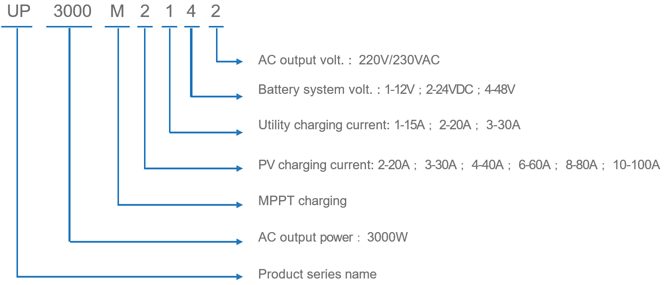
Models:
UPOWER models follow a very simple rule for naming, which is clear in the following picture.
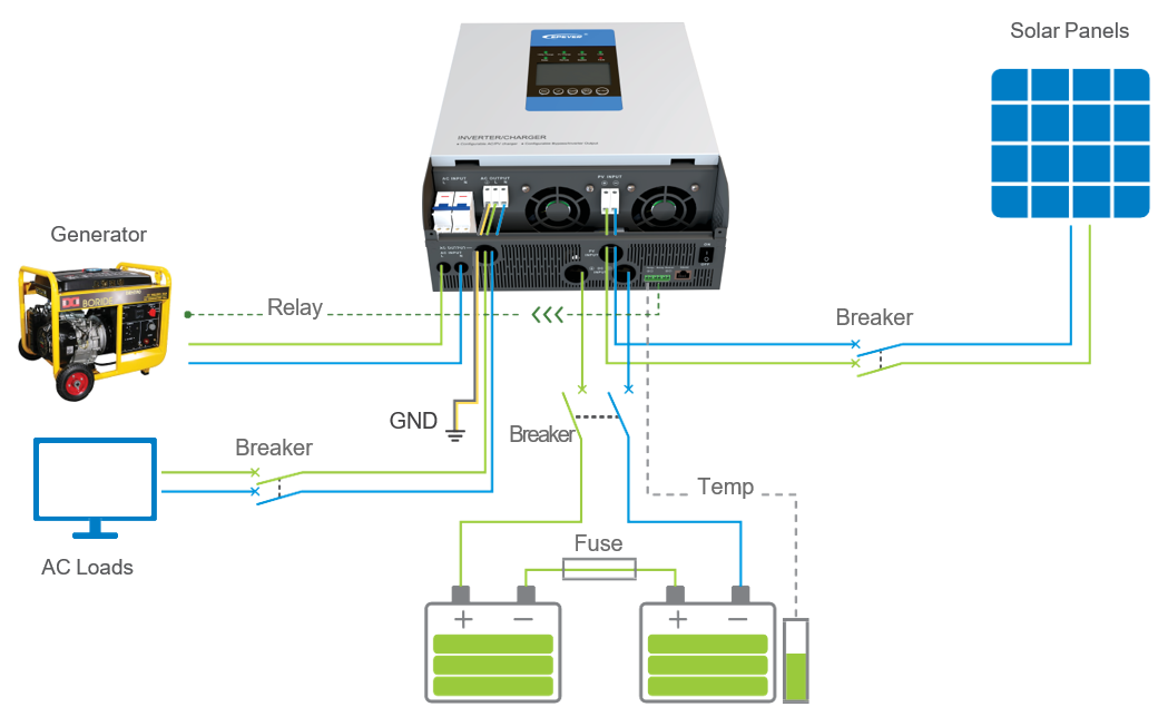
Schematic Diagram for Connections of EPEVER UPOWER Series Inverter/Charger
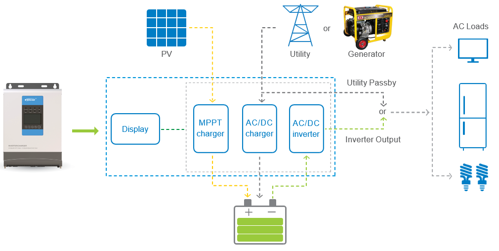
PV array
Absorbs the sun’s power and passes it to the MPPT charge controller to charge the batteries.
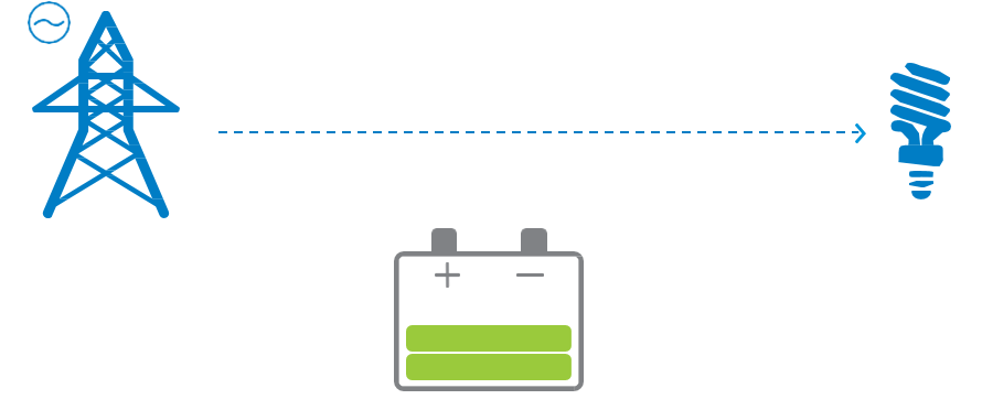
Utility
This is the additional AC power source to charge the batteries. When the source is not available, the UPOWER switches to battery power. This utility can be any external source of power in urban applications, while for off-grid systems, an external power generator can provide the energy. The AC output voltage of the UPOWER is in the range of 220-230 VAC. This means that the urban power distribution network with the 220-230 VAC output voltage can be utilized as the direct AC power source for the EPEVER UPOWER. This is called the “bypass function.”
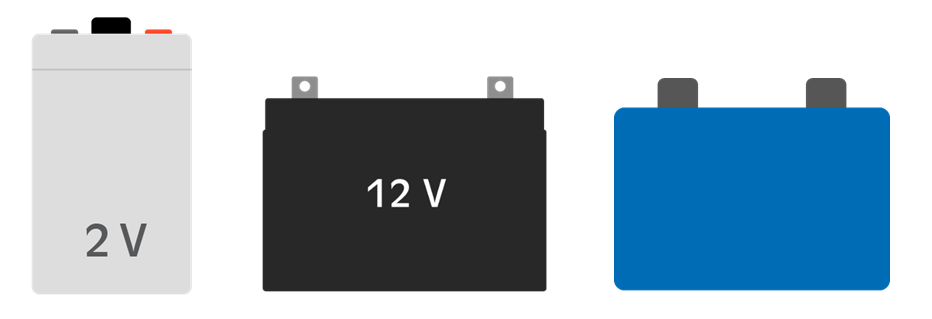
Battery
UPOWER is compatible with various types of batteries, including AGM, Gel, Flooded, etc. However, the charging parameters are fully customizable to meet the charging profile of any kind of battery.
AC load
Any AC consumer is considered as an AC load.
Installation steps
This section includes the installation guidelines for the EPEVER UPOWER series inverter/charger.
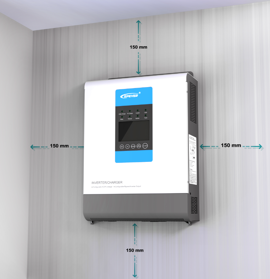
Step1:Determination of Installation Location and heat-dissipation Space
Determination of installation location: The inverter/charger shall be installed in a place with sufficient airflow through the dissipation pad of the inverter/charger and a minimum clearance of 150 mm from the upper and lower edges of the device to ensure natural thermal convection.
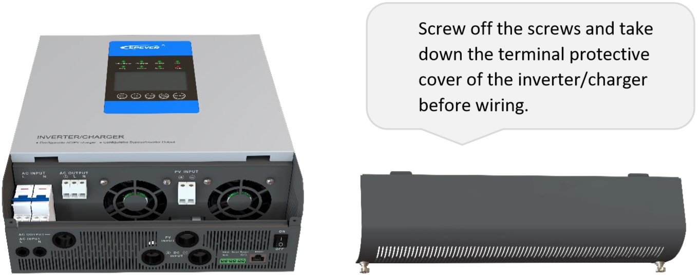
Step 2: Remove the terminal protective cover
Step 3:Wiring
Follow the wiring scheme of UPOWER as described in below picture:
Grounding
Grounding must be applied when the utility is connected to the inverter/charger. The inverter/charger has a dedicated grounding terminal, as shown in picture above. The grounding wire has to stay consistent with the recommended wire for AC output. Grounding point shall be as close as possible to the inverter/charger, the grounding wire shall be as short as possible, and if it’s not possible, its recommended to increase the wire size accordingly.
AC output, Ground and PV wiring terminals
When wiring, do not close the circuit breaker, and it is necessary to use a slotted screwdriver to unscrew the screws for connecting their corresponding wires.
When removing the wirings, first turn the UPOWER off, and then the screws shall be unscrewed by using a slotted screwdriver, so as to dismantle their corresponding wires.
Step 4: Install the terminal protective cover.
Step 5:Connect accessory
Connect the remote temperature sensor cable.
Step 6:Recheck if the wire connection is correct
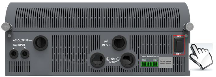
Step 7:Power on the inverter/charger
Interface Instruction
In this section, we will discuss the interface of the EPEVER UPOWER series. Indicators and buttons on the screen of the inverter/charger are investigated through subsequent tables:
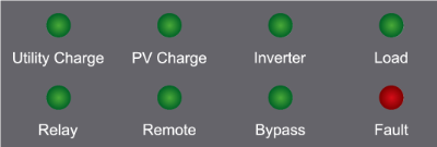
| Indicator | Color | Status | Instruction |
| Green | OFF | No utility input | |
| On Solid | Utility connection normal but no charging | ||
| Slowly Flashing(0.5Hz) | Utility charging | ||
| Fast Flashing(2.5Hz) | Utility charge module fault | ||
| Green | OFF | No PV input | |
| On Solid | PV connection normal but no charging | ||
| Slowly Flashing(0.5Hz) | PV charging | ||
| Fast Flashing(2.5Hz) | PV charge module fault | ||
| Green | OFF | Inverter turns off | |
| On Solid | Inverter turn on Bypass | ||
| Slowly Flashing(0.5Hz) | Inverter output | ||
| Fast Flashing(2.5Hz) | Inverter fault | ||
| Green | OFF | No-load output | |
| On Solid | Load output | ||
| Green | OFF | Relay turns off | |
| On Solid | Relay turn on | ||
| Green | OFF | Input voltage(3.3~12VDC) | |
| On Solid | No Input voltage | ||
| Green | OFF | Inverter output | |
| Slowly Flashing(0.5Hz) | Utility output | ||
| Red | OFF | Device normal | |
| On Solid | Device fault |
Buttons:
| Operation | instruction |
Press the  button button |
Exit the current interface |
| Press the button and hold on 2s |
Clear the faults |
Press the  or or  button button |
Browse interface: Up/Down |
| Setting interface: Up/Down | |
Press the  button button |
Switch to “Browse Parameter Column” Confirm the setting parameters |
Press the  button and hold on 2s button and hold on 2s |
Switch the” Real-Time Interface” over to “Set Browse Interface” |
| Switch the “Set Browse Interface” over to “Parameter Setting Interface” | |
Press the  button and hold on 2s button and hold on 2s |
Inverter ON/OFF |
As mentioned before, one of the prominent characteristics of the UPOWER series is various operating modes. Here we discuss these modes in both input and output parameters. First, we start from the input parameters.
Input priorities:
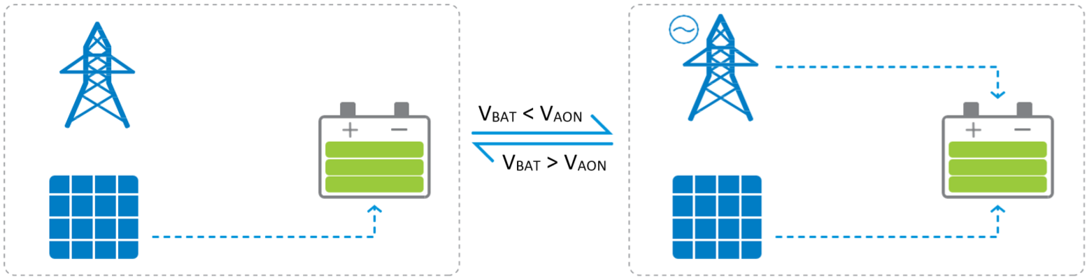
Solar priority (default)
The battery is charged in solar priority mode, and when the battery voltage is lower than “Auxiliary Module ON Voltage (VAON),” the utility starts charging. When the battery voltage reaches to “Auxiliary Module OFF Voltage (VAOF),” the utility stops charging.
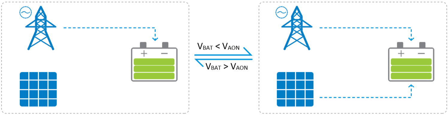
Utility priority
The battery is charged in utility priority mode, and when the battery voltage is lower than “Auxiliary Module ON Voltage (VAON),” the solar starts charging. When the battery voltage reaches to “Auxiliary Module OFF Voltage (VAOF),” the solar stops charging.
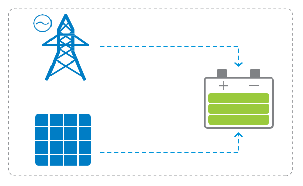
Utility & solar
Utility &solar charge the battery means that both utility and solar panels produce energy to charge the battery simultaneously, and the battery will be charged by both power sources.
Solar
In this mode, battery is charged by the solar panel, and utility is not available. The solar panel absorbs the energy and flows it to the battery.
Output Priorities
Battery
Utility (default)
As the final section, we discuss the other functions which are available by the UPOWER series inverter/charger.
Output voltage & frequency switch:
When Switch 1 is in “ON”, the output voltage is selected as 230VAC, and on the contrary as 220VAC.
When Switch 2 is in “ON”, the output frequency is selected as 60Hz, and on the contrary as 50Hz.
The switches are illustrated in the figure below.
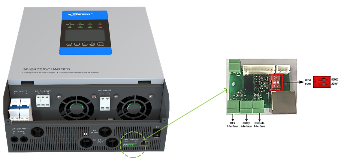
NOTE: If the output frequency or voltage of the inverter/charger is to be reset, it is required to turn off the inverter/charger and power on the unit after setting.
Technical Specification of EPEVER UPOWER Series Inverter/Charger:
| Item | UP1000-M3212 | UP1000-M3222 | UP1500-M3222 | UP2000-M3322 | UP3000-M3322 | UP3000-M6322 | ||
| System battery voltage | 12VDC | 24VDC | ||||||
| Battery input voltage range | 10.8~16VDC | 21.6~32VDC | ||||||
| Inverter Output | ||||||||
| Continuous output power | 800W | 800W | 1200W | 1600W | 2400W | 2400W | ||
| Output power (15min.) | 1000W | 1000W | 1500W | 2000W | 3000W | 3000W | ||
| Overload power(5s) | 1600W | 1600W | 2400W | 3200W | 4800W | 4800W | ||
| Max. surge power | 2000W | 2000W | 3000W | 4000W | 6000W | 6000W | ||
| Output voltage range | 220VAC±3%, 230VAC (-7%~+3%) | |||||||
| Output frequency | 50Hz/60Hz | |||||||
| Output wave | Pure Sine Wave | |||||||
| Distortion THD | ≤3% (12V or 24V resistive load) | |||||||
| Inverter efficiency | 91% | 94% | 95% | 95% | 95% | 95% | ||
| Transfer time | 20mS | |||||||
| Utility Input | ||||||||
| Utility input voltage range | 160VAC~280VAC(Working voltage range)
170VAC~270VAC(Utility starting voltage range) |
|||||||
| Max. utility charge current | 20A | 20A | 20A | 30A | 30A | 30A | ||
| Solar Charging | ||||||||
| Max. PV open circuit voltage | 60V★
46V◆ |
100V★
92V◆ |
150V★
138V◆ |
|||||
| Max. PV input power | 390W | 780W | 780W | 780W | 780W | 1500W | ||
| Max. PV charging current | 30A | 30A | 30A | 30A | 30A | 60A | ||
| Equalization voltage | 14.6V | 29.2V | ||||||
| Boost voltage | 14.4V | 28.8V | ||||||
| Float voltage | 13.8V | 27.6V | ||||||
| Tracking efficiency | ≤99.5% | |||||||
| Charging conversion efficiency | ≤98% | |||||||
| Temperature compensate coefficient | -3mV/℃/2V (Default) | |||||||
| Others | ||||||||
| No-load consumption | ≤1.2A | ≤0.6A | ≤0.6A | ≤0.8A | ≤0.8A | ≤0.8A | ||
| Enclosure | IP30 | |||||||
| Relative humidity | < 95% (N.C.) | |||||||
| Working environment temperature | -20℃~50℃(100% input and output) | |||||||
| Mechanical Parameters | ||||||||
| Dimension | 386×300×126mm | 444×300×126mm | 518×310×168mm | |||||
| Mounting dimension | 230mm | |||||||
| Mounting hole size | Φ8mm | |||||||
| Weight | 7.3kg | 7.3kg | 7.4kg | 8.5kg | 9.2kg | 14.9kg | ||
★At minimum operating environment temperature
◆At 25℃ environment temperature
| Item | UP3000-M3212 | UP3000-M3222 | UP5000-M3222 | UP5000-M3322 | UP5000-M3322 | |||
| System battery voltage | 48VDC | |||||||
| Battery input voltage range | 43.2~64VDC | |||||||
| Inverter Output | ||||||||
| Continuous output power | 2400W | 2400W | 4000W | 4000W | 4000W | |||
| Output power (15min.) | 3000W | 3000W | 5000W | 5000W | 5000W | |||
| Overload power(5s) | 4800W | 4800W | 8000W | 8000W | 8000W | |||
| Max. surge power | 6000W | 6000W | 10000W | 10000W | 10000W | |||
| Output voltage range | 220VAC±3%, 230VAC (-7%~+3%) | |||||||
| Output frequency | 50Hz/60Hz | |||||||
| Output wave | Pure Sine Wave | |||||||
| Distortion THD | ≤3% (24V or 48V resistive load) | |||||||
| Inverter efficiency | 95% | |||||||
| Transfer time | 20mS | |||||||
| Utility Input | ||||||||
| Utility input voltage range | 160VAC~280VAC(Working voltage range)
170VAC~270VAC(Utility starting voltage range) |
|||||||
| Max. utility charge current | 15A | 15A | 30A | 30A | 30A | |||
| Solar Charging | ||||||||
| Max. PV open circuit voltage | 150V
138V |
200V★
180V◆ |
||||||
| Max. PV input power | 1040W | 3000W | 3000W | 4000W | 5000W | |||
| Max. PV charging current | 20A | 60A | 60A | 80A | 100A | |||
| Equalization voltage | 58.4V | |||||||
| Boost voltage | 57.6V | |||||||
| Float voltage | 55.2V | |||||||
| Tracking efficiency | ≤99.5% | |||||||
| Charging conversion efficiency | ≤98% | |||||||
| Temperature compensate coefficient | -3mV/℃/2V (Default) | |||||||
| Others | ||||||||
| No-load consumption | ≤0.6A | ≤0.6A | ≤0.8A | ≤0.8A | ≤0.8A | |||
| Enclosure | IP30 | |||||||
| Relative humidity | < 95% (N.C.) | |||||||
| Working environment temperature | -20℃~50℃(100% input and output) | |||||||
| Mechanical Parameters | ||||||||
| Dimension | 444×300×126mm | 518×310×168mm | 614×315×178mm | |||||
| Mounting dimension | 230mm | |||||||
| Mounting hole size | Φ8mm | |||||||
| Weight | 7.3kg | 14.7kg | 16.6kg | 17.5kg | 17.8kg | |||