


In this article, we will cover the basic knowledge you will need for designing a stand-alone (off-grid) system. We will go through several steps to identify the requirements and size of the components.
Standalone systems are typically employed where there is no access to the electrical grid. A few examples are off-grid houses, RVs, boats and etc.
Here is the basic schematic for a common solar standalone system. As you can see in this diagram it has consisted of a Solar Inverter, Solar Charge Controller, Batteries (storage), Solar Panels, Optional Generator, connections, and AC loads.
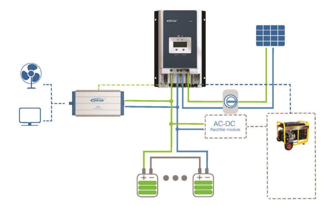
The power inverter converts the DC electricity into AC electricity. Charge controller manages the charging and discharging of the battery bank. Charge controllers usually come with two types: PWM and MPPT. MPPT charge controller tracks the maximum power point of solar panels and keeps the panels producing their higher potential. A battery bank is responsible to store the electrical energy, and to provide the required power, for a planned duration. A backup generator can be included to ensure that the power will be available during extended periods of time, or for supporting an occasionally large load.
Here are the designing steps:
Step 1: Daily power usage
Figuring out the amount of the power you need, is the first step for designing a solar off-grid system. We need to take a list of every electrical device that we are powering and how long we need to power them. Actually, for off-grid systems, we don’t have anything called “average usage” or “high usage”, and based on every single consumer, the size of the system will differ.
Typically, every electrical equipment will have a power label on it. We have AC consumers and DC consumers, and based on the type of the consumer, we may see different values on the label.
Regardless of the type of the consumer, “voltage” measured by volts, “current” measured by amperes and “power” measured by watts, are the three essential elements, we need to know, prior to reading the labels. Multiplying volts by amps get watts. Here is the simple equation for calculating the power of an AC consumer:
| Power (Watts)=Voltage (volts)×Current (Amps) |
If the voltage and current mentioned on the label, are DC values, the power is still calculated by multiplying volts to amps, however, this time, the consumed power is DC power.
Sometimes the voltage mentioned on the label is not a determined number, but is a range, for example, 110V to 250V, here we can use the grid voltage in a local area (or your Inverters output voltage) for calculating the power of the consumer.
Sometimes, the power is directly mentioned on the label, and this way, no calculations are needed to get the power of the consumer.
Watt-hours per day are the amount of energy consumed by a piece of electrical equipment during a day. In order to calculate watt-hours, we need to multiply the power to hours:
| Watt hours=Power (Watts)×hoursWatt hours=Power (Watts)×hours |
Sometimes, the consumed power is an average number for a year and is expressed by watt-hours. Here, we can divide the mentioned number by 365 (days of the year) to get the average consumed energy per day.
However, another method to calculate the power consumed by a piece of equipment is to use an energy meter, over a period of time, and get the precise value of the consumed energy.
After all, if we don’t have access to our consumers, for example when we are just pre-designing a system, or when we are not sure about the wattage of our appliances, this power consuming reference table can help us, find out the commonly associated power to different appliances.
Power consuming reference table
Kitchen Appliances
Appliance |
Watts |
Appliance |
Watts |
| Blender | 500 | Coffee Machine | 1000 |
| Dishwasher | 1200-1500 | Chest Freezer (15 cu.ft.)* | 1080 Wh/Day |
| Refrigerator (16 cu.ft.)* | 1200 Wh/Day | Garbage Disposal | 450 |
| Microwave | 1000 | Electric Oven | 1200 |
| Toaster | 850 | Toaster Oven | 1200 |
Lighting
Appliance |
Watts |
Appliance |
Watts |
| CFL Bulb – 40W Equivalent | 10 | LED Bulb – 40W Equivalent | 10 |
| CFL Bulb – 60W Equivalent | 18 | LED Bulb – 60W Equivalent | 13 |
| CFL Bulb – 75W Equivalent | 20 | LED Bulb – 75W Equivalent | 18 |
| CFL Bulb – 100W Equivalent | 30 | LED Bulb – 90W Equivalent | 23 |
| Incandescent – 50W | 50 | Halogen – 40W | 40 |
| Incandescent – 100W |
Heating & Cooling
Appliance |
Watts |
Appliance |
Watts |
| Box Fan | 200 | Furnace Fan Blower | 800 |
| Ceiling Fan | 120 | Space Heater NA | 1500 |
| Central Air Conditioner – 24,000 BTU NA | 3800 | Window Air Conditioner 12,000 BTU NA | 3250 |
| Central Air Conditioner – 10,000 BTU NA | 1200 | Window Air Conditioner 10,000 BTU NA | 1200 |
Water
Appliance |
Watts |
Appliance |
Watts |
| Well Pump – 1/3 1HP | 750 | 120V 50 Gal Water Heater-Electric | 1125 |
| 220V Tankless Water Heater-Electric | 18000 | 240V 50 Gal Water Heater-Electric | 4500 |
Laundry
Appliance |
Watts |
Appliance |
Watts |
| Electric Clothes Dryer | 3000 | Top Loading Washer | 800 |
| Gas Clothes Dryer | 1800 | Iron | 1200 |
Office
Appliance |
Watts |
Appliance |
Watts |
| Desktop Computer (Standard) | 200 | LCD Monitor | 100 |
| Laptop | 100 | Modem | 7 |
| Printer | 100 | Router | 7 |
| Smart Phone – Recharge | 6 | Tablet – Recharge | 8 |
Living Room / Electronics
Appliance |
Watts |
Appliance |
Watts |
| LCD Television | 150 | Blu Ray DVD Player | 15 |
| Plasma Television | 200 | Standard DVD Player | 15 |
| Satellite Dish | 25 | Cable Box | 35 |
| Stereo Receiver | 450 | Video Game Console | 35 |
Tools
Appliance |
Watts |
Appliance |
Watts |
| Band Saw: 1/4″ | 1100 | Disc Sander: 9″ | 1200 |
| Belt Sander: 3″ | 1000 | Drill: 1/4″ | 250 |
| Chain Saw | 1100 | Drill: 1″ | 1000 |
| Circular Saw: 7 1/4″ | 900 | Hedge Trimmer | 450 |
| Circular Saw: 8 1/4″ | 1400 | Weed Eater | 500 |
Cleaning & Personal Care
Appliance |
Watts |
Appliance |
Watts |
| Vacuum | 1000 | Clock Radio | 7 |
| Sewing Machine | 100 | Hair Dryer | 1500 |
| Dehumidifier | 280 | Electric Shaver | 15 |
| Humidifier | 200 | Curling Iron | 150 |
| Electric Blanket | 200 |
RV appliance
Appliance |
Watts |
Appliance |
Watts |
| Air Conditioner (each) | 1700 | Radio | 100 |
| Battery Charger | 1000 | Electric Drill | 500 |
| Refrigerator | 800 | Electric Broom | 300 |
| Microwave Oven | 1200 | Electric Blanket | 150 |
| Electric Frying Pan/Wok | 1200 | Portable Heater (Ceramic) | 150 |
| Electric Stove Element | 800 | Toaster | 1200 |
| Electric Water Heater (6 gallon) | 1200 | Food Processor | 750 |
| Electric Iron | 1000 | Hand Vacuum | 250 |
| Hair Dryer | 1000 | Crock Pot | 250 |
| Electric Coffee Pot | 600 | Satellite Dish and Receiver | 200 |
| Television (CRT) | 400 | Heating Pad | 100 |
Note that the power values mentioned at this table, are approximate values and to determine the exact values, the power label or power meter must be used.
Once the power consumption of each electrical appliances is determined, we can make a list of them. The load calculator helps you to do it in a simple way. Just fill out the form, and you’ll have access to your daily watt-hours.
Most of the AC appliances will require a higher power while getting started, than their nominal power. That’s called the peak (surge) power. The peak power is used to determine the inverter size, and to make sure that the inverter will support the appliances, in the case of simultaneous start-up. Another principle that plays a role in sizing an inverter, is the number of devices that are on at once. So if you have several pieces of equipment running together, make sure to check the “Running at the same time” box to run a proper size calculation for the inverter, unless your devices won’t be able to be turned on, or it will damage the inverter.
Finally, we need to take this into consideration that the DC loads, are not running through the inverter, but directly gets their needed power from the batteries. So DC loads, will not be included in sizing the inverter, and we will use this data when sizing the battery bank.
Appliance Name |
Running at the same time? |
Quantity |
AC Watts |
Peak AC Watts |
DC Watts |
Hours On per Day |
Watt-Hours / Day |
|---|---|---|---|---|---|---|---|
| DC Light | 4 | 10 | 3 | 120 | |||
| AC Light | √ | 2 | 15 | 15 | 2 | 60 | |
| Refrigerator | √ | 1 | 50 | 200 | 24 | 1200 | |
| LCD Television | √ | 1 | 150 | 150 | 3 | 450 | |
| Dishwasher | √ | 1 | 1200 | 1200 | 0.5 | 600 | |
| Laptop | √ | 1 | 80 | 80 | 3 | 240 | |
| Number of the equipment running together | Total power at once (W) | Total peak power (W) | Total daily power consumption (Watt-hours/day) | ||||
| AC | DC | ||||||
| 5 | 1510 | 2460 | 2550 | 120 | |||
Step 2: Sizing the battery bank
Now that we know how much power we consume each day, it’s now the time to determine the battery bank size. Here are the terms which determine the battery bank size:
- Daily power consumption
- System voltage
- Days of autonomy
- Depth of discharge
- Temperature
- Inverter efficiency
The Battery calculator helps you to calculate the required battery bank size in a simple way. Just fill out the form, and you’ll have access to your daily watt-hours.
Batteries are one of the most important parts of every standalone solar system. Flooded Lead Acid Batteries, Sealed Lead Acid Batteries, Lithium Batteries are the commonly used batteries in the market. Systems application, budget, and expectations for back-up time are those factors that play a role in picking the right battery type. The type of batteries used in solar PV systems is a deep cycle or solar batteries which are able to produce consistent power output while being discharged to a greater extent than a typical battery. Lithium batteries, also have a longer lifespan and get charged faster. Deeper discharge rate means lower capacities in battery sizing.
A battery is recognized with its voltage (V) and capacity measured by amp-hours (AH). To provide desired system voltage, one can wire the batteries in series and parallel. Wiring strings in series, increased the voltage, while wiring in parallel, adds up the total battery bank capacity. However, it’s not recommended to have more than two parallel strings on a system, since a little voltage mismatch in strings, will lead to a shorter lifespan of the batteries. A battery banks voltage should be coordinated with the solar array voltage, to ensure proper charging. However, an MPPT charge controller will step the input voltage of the solar arrays, down and up to adjust it with the battery voltage. Inverter power is one of the factors that play a role in determining the size of the system. Since the inverters usually support a single input voltage (12V, 24V, 36V, and 48V) then the type and size of the inverter, is an intersecting parameter while choosing the system voltage. The higher the inverter size is, usually it comes with higher DC input values. Additionally, increasing the voltage of the system, will reduce the power loss in wiring elements, and therefore will lead to the higher performance of the total system.
The capacity of a battery bank rated by amp-hours indicates how much energy it can store and therefore how much back up time, the stand-alone system will provide for loads. Once we know how much power we need a day, it also needed to determine how many days, we want to run our equipment off the battery bank, when there is no sun to recharge the batteries. This is called days of autonomy. The bigger the days of autonomy is, the longer the backup time and the higher the number of batteries will come with the system. This is a matter of cost, therefore using an external generator is a great way, to reduce the number of days of autonomy. This means that for example, if we are planning for more than 3 days, then we can use a generator to charge the batteries in the last day and reduce the battery bank costs.
The depth of discharge (DOD) is also used for designing the battery bank. Besides the voltage and capacity, the other primary design decision is how much to let the batteries discharge.
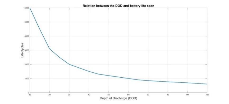
As you can see in this figure, the more a battery is allowed to discharge, the shorter its lifespan. While allowing batteries to discharge more seems to be cost-effective, but this way the batteries won’t last long. Deep cycle batteries are designed to discharge 80% of their capacity, but it recommended to choose a value of around 50% as a good trade-off between longevity, cost, and the hassle of replacing batteries. If the days of autonomy is more than one day, the actual DOD on a sunny day will be less than 20% resulting in a higher lifespan.
Temperature is another term that should be taken into consideration while calculating battery bank size.
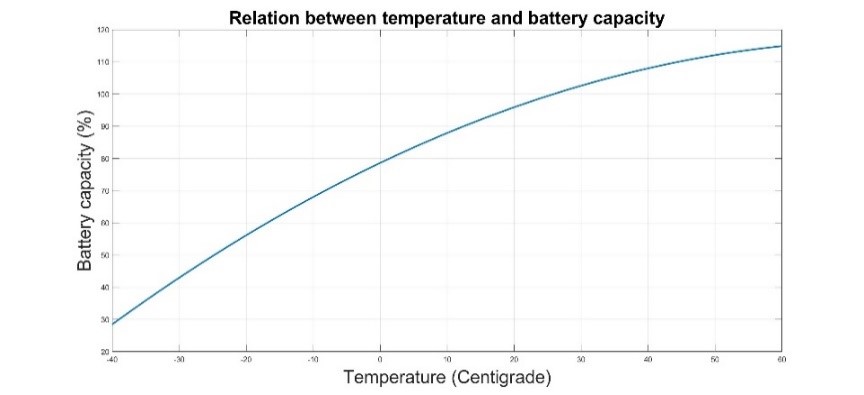
Battery capacity is usually rated in standard temperature 25o C (77o F). As shown in the figure, when the temperate varies, the capacity also varies. In higher temperatures, batteries have higher capacities and in lower temperatures, it’s vice versa. The colder the battery is, the larger the capacity needs to be. So it’s better to consider the coldest days of the year while calculating the system. Temperature coefficient can be extracted from this figure, which will be used in battery bank calculations.
Inverter efficiency is another term which effects the battery size. There are no ideal inverters and there is a power loss, converting DC to AC. So this loss should be taken into consideration while calculating the power bank size.
The equations are as below:
| Battery Bank Capacity (AH)=(AC LoadsInverter efficiency+DC Loads) × Days of autonomy × Temp. CoefficientDepth of discharge × System voltage |
Here is a simple example of a battery bank calculation. We have a daily consumption of 2550Watts AC load and 120W DC load. We need 2 days of autonomy. We will use the battery in 50% depth of discharge. The coldest temperature that batteries will experience is this example, is -10o C. System voltage is 48V and the inverter efficiency is 95%. So we have:
| Battery Bank Capacity (AH)=(25500.95+120) × 2 × (1.47) 50% × 48
Battery Bank Capacity (AH)=(25500.95+120) × 2 × (1.47) 50% × 48 |
Depending on the battery voltage and capacity, the total number of batteries will be determined. The number of strings determines the minimum amp-hours capacity of each battery, and system voltage determines the number of the batteries needs to be in series.
| Minimum Battery Capacity (AH)=Battery Bank Capacity (AH)Number of parallel battery strings |
So in this example, if we consider two parallel strings, we have:
| Minimum Battery Capacity (AH)=344 AH2=171 AH |
So for example, a 12V 170Ah battery looks like suitable for this purpose.
The final step is to determine the number of batteries in each string. This is calculated by dividing the system voltage, to battery voltage:
| Number of batteries in each string=System VoltageBattery Voltage |
So in our example:
| Number of batteries in each string=48V12V=4 |
Therefore, in each parallel string, there should be 4 pieces of 12V batteries.
The total number of required batteries is:
| Total number of required batteries=Number of strings×Number of batteries in each string |
And for this example we have:
| Total number of required batterie s=2 × 4=8 |
AC Load (W) |
DC Load (W) |
Days of autonomy |
DOD |
Temperature(oC) |
Inverter Efficiency |
System Voltage (V) |
Number of parallel strings |
Battery Voltage (V) |
| 2550 | 120 | 2 | 0.5 | -10 | 0.95 | 48 | 2 | 12 |
| Total battery bank capacity (AH) | Minimum battery capacity (AH) | Number of batteries in each string | Total number of required batteries | |||||
| 344 | 171 | 4 | 8 | |||||
Step 3: How many solar panels do I need?
The number of solar panels used in an off-grid system depends on several factors.
- Daily energy consumption
- Days of autonomy
- Geographical location and least number of sun hours for the worst days of the year
- Solar panels efficiency
- Shading, Wiring and System losses
- Solar panels tilt and azimuth angles
The power produced by a solar array is measured in watts and is equal to the current multiplied by the voltage. Labels of solar panels contain useful information about the array. Voc
Vocand Isc
Iscare the two important characteristics we use in designing standalone solar systems. Voc
Vocor open circuit occurs when the positive and negative leads from of a solar array are not connected and this will result in the highest voltage the cell can produce, called open circuit voltage of the PV array. Isc
Iscor short circuit current occurs when the positive and negative leads are connected directly together, resulting in the highest current the array can produce. These two, are important characteristics of any module used for determining charge controller capacity, wire sizing, fuse sizing, and other equipment that will be required. Sunlight intensity and array temperature, are two parameters which affect the produced power by the solar arrays. Solar array voltage does not change much at different irradiation levels, but the current output is proportional to the amount of sunlight falling on the array. Temperature decreases the generated power of a solar array. Depending on the properties of the semiconductor material, de-rating differs from an array to the other. So the panels with lower temperature coefficient will produce higher energy in peak operating conditions.
Different locations of the world, get different levels of daily sun irradiations. The actual generated power from solar arrays at any location depends on the latitude, the time of day and year, any shading from adjacent buildings or trees, the mounting angle of the solar array and the local weather. In order to take all these factors into account, we recommend using software such as “PVSYST”. But here we will use a simple rule. We will consider the worst condition when it is the coldest days of the year and we have the minimum sun-hours with no shadings on the solar array. We assume that the array is tilted at the latitude and facing the south.
Here is the simple equation to calculate the amount of the required solar panels:
| Required solar panels (Watts)=Daily load × Days of autonomyWorst sun hours of the year × System efficiency |
In our example, we have about 2670Watts daily power consumption, and we consider two days of autonomy for the project. We consider a location with 3.5 sun-hours (the worst case), and with 70% system efficiency. So we have:
| Required solar panels (Watts)=2670 × 23.5 × 0.7=2179W |
Solar arrays can be wired in series and parallel. Based on the charge controller type, one can select different types of panels. The number of the panels needed is calculated as below:
| Number of solar panels=Required solar panels (Watts)Selected panels power |
So, for this example, if we choose 335W panels, we have:
| Number of solar panels=2179W335W=6.5≅6 |
So for this project, we will need 6 pieces of 335W solar panels.
However, it should be noted that the design is done restrictedly with the lowest amount of running out power, even at the cold winter days, with low sun-hours.
The solar panel calculator will help to ease the calculation process.
Total daily load (V) |
Days of autonomy |
Worst sun-hours a day (Hours) |
System efficiency |
Chosen solar panel power (W) |
| 2670 | 2 | 3.5 | 0.7 | 335 |
| Required solar panels (Watts) | Number of required solar panels (rounded up) | |||
| 2179 | 6 | |||
Step 4: Charge controller
Certain parameters are included in sizing a charge controller:
- The wattage of the solar arrays
- Voc Voc and Isc Isc of the solar panels
- System voltage
PWM and MPPT charge controllers are the two common types of controllers used in standalone solar projects. There are certain differences between these two controllers and it is covered in another article. A PWM charge controller connects and disconnects the solar array to the batteries and charges the batteries, according to their voltage. This means that the array’s voltage comes down to the battery’s voltage and the power transmission is not efficient. Using a PWM charge controller, we need to make sure that the nominal voltage of the solar array, is matched with the batteries voltage. Maximum Power Point Tracking (MPPT) is a kind of charging control technology that ensures delivering the maximum available power, from the solar array to the charge controllers. Unlike PWM controllers, MPPT charge controllers can pair non-matching voltages from panels and batteries. The technology is mainly composed of BUCK circuit and controls the working voltage of the PV panel near the max power point. An MPPT controller reduces the array voltage near the battery voltage and increases the current to get the maximum energy available from the solar arrays.
Voc
Vocand Isc
Iscof the solar panels are also important in calculating the capacity of the controller. Charge controllers have limited input and output voltage and current. While designing the controller, the voltage of the PV arrays and their generated current must be taken into consideration. The controller should tolerate these amounts unless it will damage the controller. Here is the simple equation for calculating the controller size:
| Charge controller current capacity=solar panels power (Watts)system voltage×Safety factor |
For our example, we have 6 pieces of 335W solar panels, and the system voltage is 48Volts, so we have:
| Charge controller current capacity=6 × 335W48V×1.3=54.4A |
So a 60A MPPT charge controller will be a good choice.
This equation works for both MPPT and PWM. However, there are a few notes, covered in Charge Controller page.
Step 5: Inverter
Here are the parameters included in sizing and choosing an Inverter:
- Total AC Watts at the same time.
- Total AC peak power
- System Voltage
- Output voltage and frequency
Total AC Watts at the same time, determine the nominal AC output power of the inverter. To obtain this number, just add up those power of the equipment that is running together at the same time. Doing the same process for peak powers of the equipment will lead to total AC peak power. The inverter should support both of these values. However it’s recommended not to use an inverter in its 100% capacity (due to power degrade and some other factors), so choosing a slightly bigger power for the inverter, will result in better performance of the total system. The input battery voltage range of the inverter should support the system voltage. The common output voltage of an off-grid solar system will be 120/240VAC, based on the location. Additionally, 50/60Hz are the two common optional frequencies of an inverter’s output.
So in our example, we have 1495W AC loads ON at the same time and the cumulative peak power of 2445W. So a 2KW inverter, which tolerates 4000W peak power for a while, will be a good choice for our example.